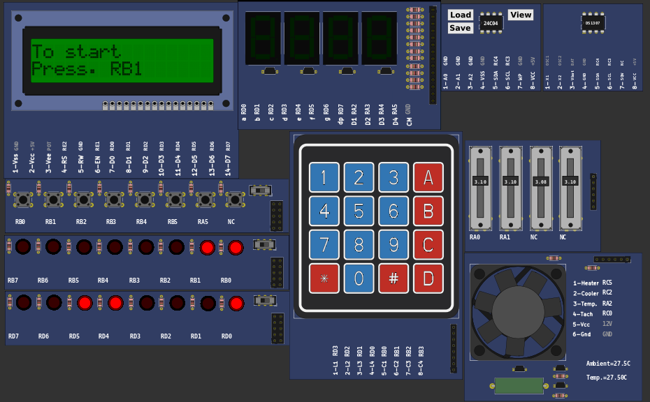
[Breadboard/PIC16F777/test_b0]Simple example for testing board features.1- Ask to turn on all dip switches; 2- Tests LCD display; 3- Tests 7-segment displays; 4- Test the red LEDs connected to the PORTB and PORTD; 5- Tests push buttons; 6- Test the serial port transmitting; 7- Test the serial port receiving; 8- Tests AD converters connected to potentiometers; 9- Test Relays 10- Tests temperature measurement; 11- Turn on the Heater; 12- Turn on the fan and measure the speed. 13- Tests the matrix keyboard 14- Tests internal eepromMPLABX test_b0 project | |
 |
Download (pzw)
View Online |
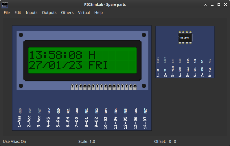
[Breadboard/PIC16F877A/DS1307]DS1307 RTCInterfacing Real Timer Clock (DS1307) with PIC MicrocontrollerSource Code | |
 |
Download (pzw)
View Online |
[Breadboard/PIC16F877A/test_b0]Simple example for testing board features.1- Ask to turn on all dip switches; 2- Tests LCD display; 3- Tests 7-segment displays; 4- Test the red LEDs connected to the PORTB and PORTD; 5- Tests push buttons; 6- Test the serial port transmitting; 7- Test the serial port receiving; 8- Tests AD converters connected to potentiometers; 9- Test Relays 10- Tests temperature measurement; 11- Turn on the Heater; 12- Turn on the fan and measure the speed. 13- Tests the matrix keyboard 14- Tests internal eepromMPLABX test_b0 project | |
 |
Download (pzw)
View Online |
[Breadboard/PIC18F452/test_b0]Simple example for testing board features.1- Ask to turn on all dip switches; 2- Tests LCD display; 3- Tests 7-segment displays; 4- Test the red LEDs connected to the PORTB and PORTD; 5- Tests push buttons; 6- Test the serial port transmitting; 7- Test the serial port receiving; 8- Tests AD converters connected to potentiometers; 9- Test Relays 10- Tests temperature measurement; 11- Turn on the Heater; 12- Turn on the fan and measure the speed. 13- Tests the matrix keyboard 14- Tests internal eepromMPLABX test_b0 project | |
 |
Download (pzw)
View Online |
[Breadboard/PIC18F4550/test_b0]Simple example for testing board features.1- Ask to turn on all dip switches; 2- Tests LCD display; 3- Tests 7-segment displays; 4- Test the red LEDs connected to the PORTB and PORTD; 5- Tests push buttons; 6- Test the serial port transmitting; 7- Test the serial port receiving; 8- Tests AD converters connected to potentiometers; 9- Test Relays 10- Tests temperature measurement; 11- Turn on the Heater; 12- Turn on the fan and measure the speed. 13- Tests the matrix keyboard 14- Tests internal eepromMPLABX test_b0 project | |
 |
Download (pzw)
View Online |
[Breadboard/PIC18F4620/DS1307]DS1307 RTCInterfacing Real Timer Clock (DS1307) with PIC MicrocontrollerSource Code | |
 |
Download (pzw)
View Online |
[Breadboard/PIC18F4620/test_b0]Simple example for testing board features.1- Ask to turn on all dip switches; 2- Tests LCD display; 3- Tests 7-segment displays; 4- Test the red LEDs connected to the PORTB and PORTD; 5- Tests push buttons; 6- Test the serial port transmitting; 7- Test the serial port receiving; 8- Tests AD converters connected to potentiometers; 9- Test Relays 10- Tests temperature measurement; 11- Turn on the Heater; 12- Turn on the fan and measure the speed. 13- Tests the matrix keyboard 14- Tests internal eepromMPLABX test_b0 project | |
 |
Download (pzw)
View Online |
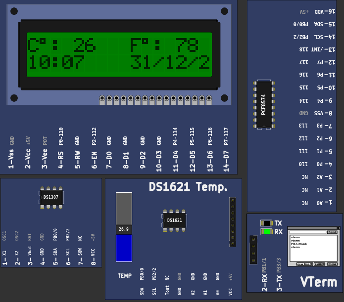
[Franzininho_DIY/attiny85/Tiny85_Temp_LCD_RTC] Example Tiny85 Temp LCD RTC of TinyWireM libraryATtiny85 as an I2C Master Ex3 BroHogan 1/22/11 I2C master reading DS1621 temperature sensor & DS1307 RTC. Display to I2C GPIO LED. SETUP: ATtiny Pin 1 = (RESET) N/U ATtiny Pin 2 = (D3) N/U ATtiny Pin 3 = (D4) to LED1 ATtiny Pin 4 = GND ATtiny Pin 5 = SDA on all devices ATtiny Pin 6 = (D1) to LED2 ATtiny Pin 7 = SCK on all devices ATtiny Pin 8 = VCC (2.7-5.5V) NOTE! - It's very important to use pullups on the SDA & SCL lines! DS1621 wired per data sheet. This ex assumes A0-A2 are set LOW for an addeess of 0x48 DS1307 wired per data sheet. This ex assumes A0-A2 are set LOW for an addeess of 0x68 PCA8574A GPIO was used wired per instructions in "info" folder in the LiquidCrystal_I2C lib. This ex assumes A0-A2 are set HIGH for an addeess of 0x3F LiquidCrystal_I2C lib was modified for ATtiny - on Playground with TinyWireM lib. TinyWireM USAGE & CREDITS: - see TinyWireM.h Link to source code: Tiny85_Temp_LCD_RTC.pde | |
 |
Download (pzw)
View Online |