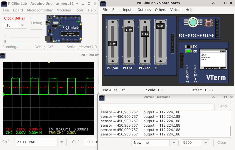
[Arduino_Uno/atmega328p/AnalogInOutSerial] Analog input, analog output, serial output
  Reads an analog input pin, maps the result to a range from 0 to 255 and uses
  the result to set the pulse width modulation (PWM) of an output pin.
  Also prints the results to the Serial Monitor.

  The circuit:
  - potentiometer connected to analog pin 0.
    Center pin of the potentiometer goes to the analog pin.
    side pins of the potentiometer go to +5V and ground
  - LED connected from digital pin 9 to ground

  created 29 Dec. 2008
  modified 9 Apr 2012
  by Tom Igoe

  This example code is in the public domain.

  http://www.arduino.cc/en/Tutorial/AnalogInOutSerial
AnalogInOutSerial.ino | |
 |
Download (pzw)
View Online |
[Arduino_Uno/atmega328p/Arduino_sound] Arduino Star Wars Song for PiezoNick James nicksort https://gist.github.com/nicksort/4736535arduino_sound.ino | |
 |
Download (pzw)
View Online |
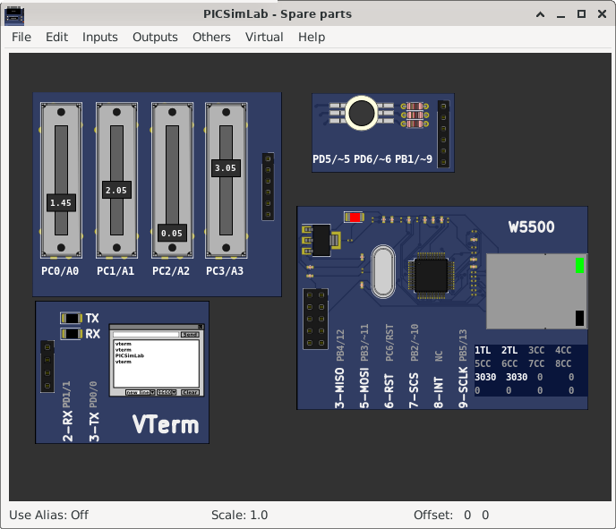
[Arduino_Uno/atmega328p/firmata_ethernet] Firmata Library - Standard Firmata EthernetStandardFirmataEthernet is a TCP client/server implementation. You will need a Firmata client library with a network transport that can act as a TCP server or client in order to establish a connection between StandardFirmataEthernet and the Firmata client application. To use StandardFirmataEthernet you will need to have one of the following boards or shields: - Arduino Ethernet shield (or clone) - Arduino Ethernet board (or clone) - Arduino Yun Follow the instructions in the ethernetConfig.h file (ethernetConfig.h tab in Arduino IDE) to configure your particular hardware. NOTE: If you are using an Arduino Ethernet shield you cannot use the following pins on the following boards. Firmata will ignore any requests to use these pins: - Arduino Uno or other ATMega328 boards: (D4, D10, D11, D12, D13) - Arduino Mega: (D4, D10, D50, D51, D52, D53) - Arduino Leonardo: (D4, D10) - Arduino Due: (D4, D10) - Arduino Zero: (D4, D10) If you are using an ArduinoEthernet board, the following pins cannot be used (same as Uno): - D4, D10, D11, D12, D13 StandardFirmataEthernet.ino | |
 |
Download (pzw) |
[Arduino_Uno/atmega328p/firmata] Firmata Library - Standard FirmataFirmata is a generic protocol for communicating with microcontrollers from software on a host computer. It is intended to work with any host computer software package. To download a host software package, please click on the following link to open the list of Firmata client libraries in your default browser. https://github.com/firmata/arduino#firmata-client-libraries Copyright (C) 2006-2008 Hans-Christoph Steiner. All rights reserved. Copyright (C) 2010-2011 Paul Stoffregen. All rights reserved. Copyright (C) 2009 Shigeru Kobayashi. All rights reserved. Copyright (C) 2009-2016 Jeff Hoefs. All rights reserved. This library is free software; you can redistribute it and/or modify it under the terms of the GNU Lesser General Public License as published by the Free Software Foundation; either version 2.1 of the License, or (at your option) any later version. See file LICENSE.txt for further informations on licensing terms. Last updated August 17th, 2017 StandardFirmata.ino | |
 |
Download (pzw) |
[Blue_Pill/stm32f103c8t6/GPIO] STM32 GPIO ExampleOriginal Link: https://blog.avislab.com/stm32-gpio/Source code | |
 |
Download (pzw) |
[Breadboard/PIC16F1619/blinkRGB]Blink RGB LEDSimple code example to blink one RGB LED. MPLABX blinkRGB project | |
 |
Download (pzw)
View Online |
[Breadboard/PIC16F1788/blinkRGB]Blink RGB LEDSimple code example to blink one RGB LED. MPLABX blinkRGB project | |
 |
Download (pzw)
View Online |
[Breadboard/PIC16F18324/blinkRGB]Blink RGB LEDSimple code example to blink one RGB LED. MPLABX blinkRGB project | |
 |
Download (pzw)
View Online |
[Breadboard/PIC16F18855/blinkRGB]Blink RGB LEDSimple code example to blink one RGB LED. MPLABX blinkRGB project | |
 |
Download (pzw)
View Online |
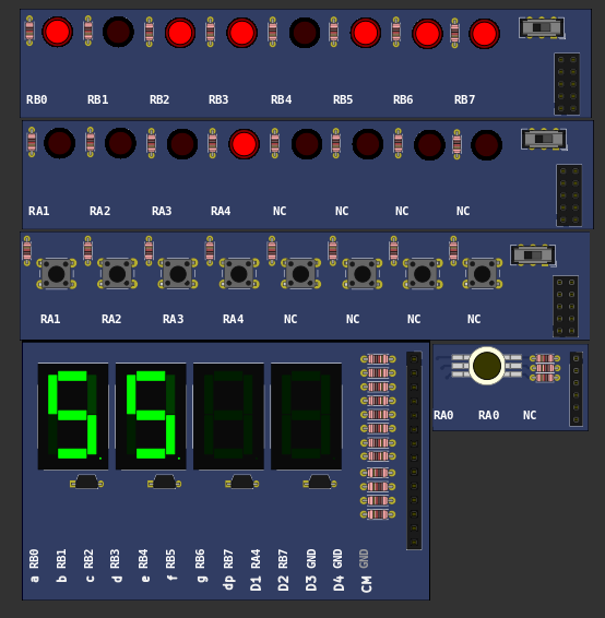
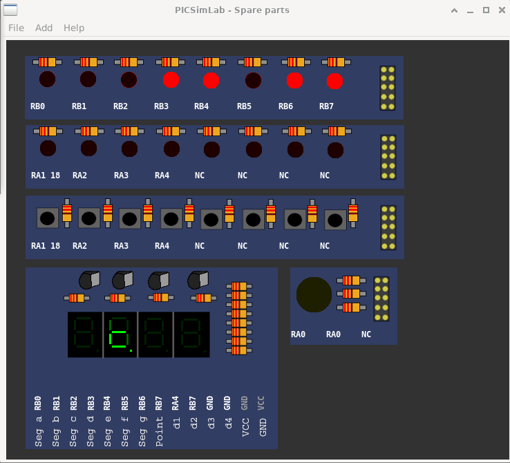
[Breadboard/PIC16F628A/test_b0]Simple example for testing board features.1- Tests 7-segment display; 2- Lamp flashes in RA0 (At this moment, change the jumper position to "LED"); 3- Tests red LEDs connected to the PORTB; 4- Test the buttons; 5- Test the green LEDs connected to the PORTA.MPLABX test_b0 project | |
 |
Download (pzw)
View Online |
[Breadboard/PIC16F648A/test_b0]Simple example for testing board features.1- Tests 7-segment display; 2- Lamp flashes in RA0 (At this moment, change the jumper position to "LED"); 3- Tests red LEDs connected to the PORTB; 4- Test the buttons; 5- Test the green LEDs connected to the PORTA.MPLABX test_b0 project | |
 |
Download (pzw)
View Online |
[Breadboard/PIC16F84A/test_b0]Simple example for testing board features.1- Tests 7-segment display; 2- Lamp flashes in RA0 (At this moment, change the jumper position to "LED"); 3- Tests red LEDs connected to the PORTB; 4- Test the buttons; 5- Test the green LEDs connected to the PORTA.MPLABX test_b0 project | |
 |
Download (pzw)
View Online |
[Breadboard/PIC16F886/blinkRGB]Blink RGB LEDSimple code example to blink one RGB LED. MPLABX blinkRGB project | |
 |
Download (pzw)
View Online |
[Breadboard/PIC18F26K80/blinkRGB]Blink RGB LEDSimple code example to blink one RGB LED. MPLABX blinkRGB project | |
 |
Download (pzw)
View Online |
[Breadboard/PIC18F27K40/blinkRGB]Blink RGB LEDSimple code example to blink one RGB LED. MPLABX blinkRGB project | |
 |
Download (pzw)
View Online |
[Breadboard/PIC18F4580/blinkRGB]Blink RGB LEDSimple code example to blink one RGB LED. MPLABX blinkRGB project | |
 |
Download (pzw)
View Online |
[Breadboard/PIC18F46J50/blinkRGB]Blink RGB LEDSimple code example to blink one RGB LED. MPLABX blinkRGB project | |
 |
Download (pzw)
View Online |
[Breadboard/PIC18F47K40/blinkRGB]Blink RGB LEDSimple code example to blink one RGB LED. MPLABX blinkRGB project | |
 |
Download (pzw)
View Online |
[Breadboard/PIC18F67J94/blinkRGB]Blink RGB LEDSimple code example to blink one RGB LED. MPLABX blinkRGB project | |
 |
Download (pzw)
View Online |
[gpboard/pic16f628a/test_b0]Exemplo simples para teste dos recursos da placa.1- Testa display de 7 segmentos; 2- Pisca lâmpada em RA0 (Neste momento trocar posição do jumper para "LED"); 3- Testa LEDs vermelhos ligados ao PORTB; 4- Testa os botões; 5- Testa os LEDs verdes ligados ao PORTA.MPLABX test_b1 project Others compilers test_b1 project | |
 |
Download (pzw)
View Online |