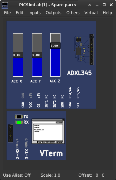
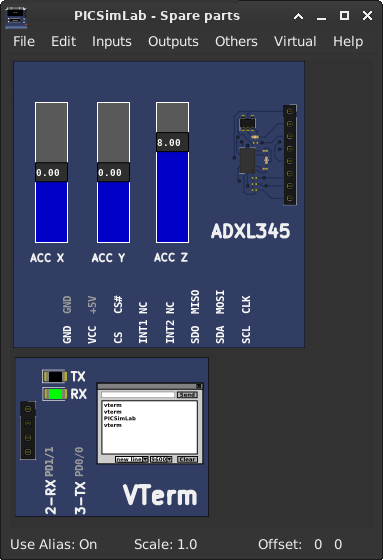
[Arduino_Uno/atmega328p/ADXL345_I2C] ADXL345 Accel example I2C/* ********************************************* * SparkFun_ADXL345_Example * Triple Axis Accelerometer Breakout - ADXL345 * Hook Up Guide Example * * Utilizing Sparkfun's ADXL345 Library * Bildr ADXL345 source file modified to support * both I2C and SPI Communication * * E.Robert @ SparkFun Electronics * *********************************************/ SparkFun_ADXL345_Example.ino | |
 |
Download (pzw)
View Online |
[Arduino_Uno/atmega328p/ADXL345_SPI] ADXL345 Accel example SPI/* ********************************************* * SparkFun_ADXL345_Example * Triple Axis Accelerometer Breakout - ADXL345 * Hook Up Guide Example * * Utilizing Sparkfun's ADXL345 Library * Bildr ADXL345 source file modified to support * both I2C and SPI Communication * * E.Robert @ SparkFun Electronics * *********************************************/ SparkFun_ADXL345_Example.ino | |
 |
Download (pzw)
View Online |
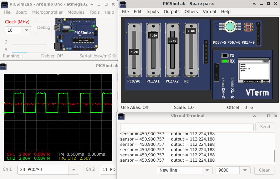
[Arduino_Uno/atmega328p/AnalogInOutSerial] Analog input, analog output, serial output
  Reads an analog input pin, maps the result to a range from 0 to 255 and uses
  the result to set the pulse width modulation (PWM) of an output pin.
  Also prints the results to the Serial Monitor.

  The circuit:
  - potentiometer connected to analog pin 0.
    Center pin of the potentiometer goes to the analog pin.
    side pins of the potentiometer go to +5V and ground
  - LED connected from digital pin 9 to ground

  created 29 Dec. 2008
  modified 9 Apr 2012
  by Tom Igoe

  This example code is in the public domain.

  http://www.arduino.cc/en/Tutorial/AnalogInOutSerial
AnalogInOutSerial.ino | |
 |
Download (pzw)
View Online |
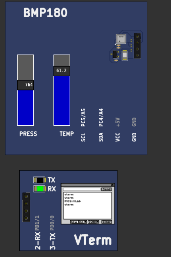
[Arduino_Uno/atmega328p/BMP180] BMP180 Pressure sensorThis is an example for the BMP085 Barometric Pressure & Temp Sensor Designed specifically to work with the Adafruit BMP085 Breakout ----> https://www.adafruit.com/products/391 These pressure and temperature sensors use I2C to communicate, 2 pins are required to interface Adafruit invests time and resources providing this open source code, please support Adafruit and open-source hardware by purchasing products from Adafruit! Written by Limor Fried/Ladyada for Adafruit Industries. BSD license, all text above must be included in any redistribution BMP085test.ino | |
 |
Download (pzw)
View Online |
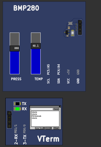
[Arduino_Uno/atmega328p/BMP280] BMP280 Pressure sensorThis is a library for the BMP280 humidity, temperature & pressure sensor Designed specifically to work with the Adafruit BMP280 Breakout ----> http://www.adafruit.com/products/2651 These sensors use I2C or SPI to communicate, 2 or 4 pins are required to interface. Adafruit invests time and resources providing this open source code, please support Adafruit andopen-source hardware by purchasing products from Adafruit! Written by Limor Fried & Kevin Townsend for Adafruit Industries. BSD license, all text above must be included in any redistribution bmp280test.ino | |
 |
Download (pzw)
View Online |
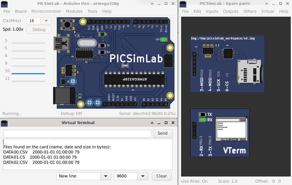
[Arduino_Uno/atmega328p/cardinfo] SD card test
  This example shows how use the utility libraries on which the'
  SD library is based in order to get info about your SD card.
  Very useful for testing a card when you're not sure whether its working or not.

  The circuit:
    SD card attached to SPI bus as follows:
 ** MOSI - pin 11 on Arduino Uno/Duemilanove/Diecimila
 ** MISO - pin 12 on Arduino Uno/Duemilanove/Diecimila
 ** CLK - pin 13 on Arduino Uno/Duemilanove/Diecimila
 ** CS - depends on your SD card shield or module.
 		Pin 4 used here for consistency with other Arduino examples


  created  28 Mar 2011
  by Limor Fried
  modified 9 Apr 2012
  by Tom Igoe
Click on sdcard connector to change sdcard file image. CardInfo.ino | |
 |
Download (pzw)
View Online |
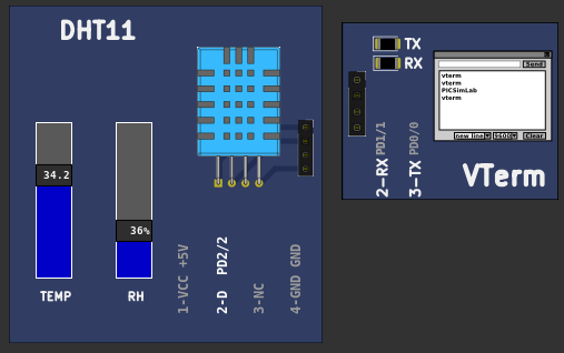
[Arduino_Uno/atmega328p/DHT11] DHT11 humidity and temperature sensor// Example testing sketch for various DHT humidity/temperature sensors // Written by ladyada, public domain // // REQUIRES the following Arduino libraries: // - DHT Sensor Library: https://github.com/adafruit/DHT-sensor-library // - Adafruit Unified Sensor Lib: https://github.com/adafruit/Adafruit_Sensor DHTtester.ino | |
 |
Download (pzw)
View Online |
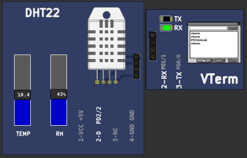
[Arduino_Uno/atmega328p/DHT22] DHT22 humidity and temperature sensor// Example testing sketch for various DHT humidity/temperature sensors // Written by ladyada, public domain // // REQUIRES the following Arduino libraries: // - DHT Sensor Library: https://github.com/adafruit/DHT-sensor-library // - Adafruit Unified Sensor Lib: https://github.com/adafruit/Adafruit_Sensor DHTtester.ino | |
 |
Download (pzw)
View Online |
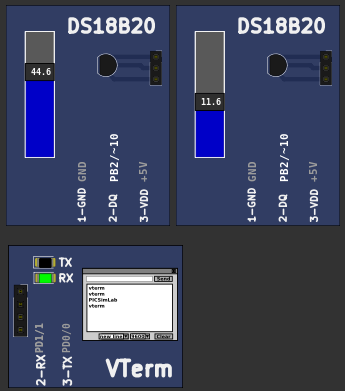
[Arduino_Uno/atmega328p/DS18B20] DS18S20 Temperature sensor// OneWire DS18S20, DS18B20, DS1822 Temperature Example // // http://www.pjrc.com/teensy/td_libs_OneWire.html // // The DallasTemperature library can do all this work for you! // https://github.com/milesburton/Arduino-Temperature-Control-Library DS18x20_Temperature.ino | |
 |
Download (pzw)
View Online |
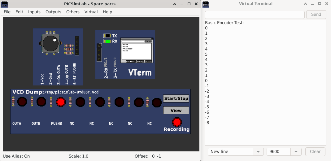
[Arduino_Uno/atmega328p/Encoder_basic] Encoder Library - Basic Example/* Encoder Library - Basic Example * http://www.pjrc.com/teensy/td_libs_Encoder.html * * This example code is in the public domain. */ Basic.pde | |
 |
Download (pzw)
View Online |
[Arduino_Uno/atmega328p/firmata_ethernet] Firmata Library - Standard Firmata EthernetStandardFirmataEthernet is a TCP client/server implementation. You will need a Firmata client library with a network transport that can act as a TCP server or client in order to establish a connection between StandardFirmataEthernet and the Firmata client application. To use StandardFirmataEthernet you will need to have one of the following boards or shields: - Arduino Ethernet shield (or clone) - Arduino Ethernet board (or clone) - Arduino Yun Follow the instructions in the ethernetConfig.h file (ethernetConfig.h tab in Arduino IDE) to configure your particular hardware. NOTE: If you are using an Arduino Ethernet shield you cannot use the following pins on the following boards. Firmata will ignore any requests to use these pins: - Arduino Uno or other ATMega328 boards: (D4, D10, D11, D12, D13) - Arduino Mega: (D4, D10, D50, D51, D52, D53) - Arduino Leonardo: (D4, D10) - Arduino Due: (D4, D10) - Arduino Zero: (D4, D10) If you are using an ArduinoEthernet board, the following pins cannot be used (same as Uno): - D4, D10, D11, D12, D13 StandardFirmataEthernet.ino | |
 |
Download (pzw) |
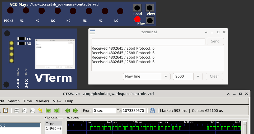
[Arduino_Uno/atmega328p/rc_receiver] library rc-switch example: ReceiveDemo Simple/* Simple example for receiving https://github.com/sui77/rc-switch/ */ Press the play button on VCD play part to send the recorded code to microcontroller input. ReceiveDemo_Simple.ino | |
 |
Download (pzw)
View Online |
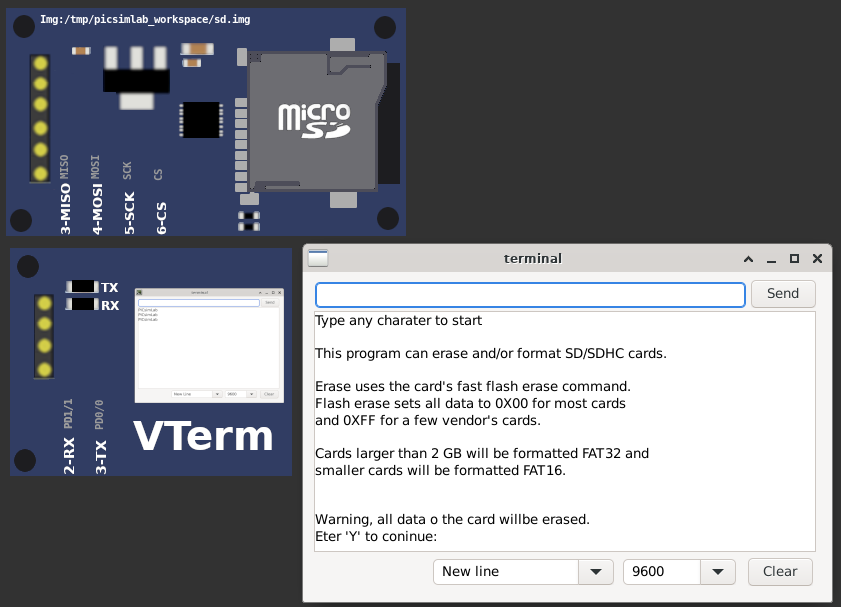
[Arduino_Uno/atmega328p/sdformatter] Sd Formatter/* * This program will format SD/SDHC/SDXC cards. * Warning all data will be deleted! * * This program attempts to match the format * generated by SDFormatter available here: * * http://www.sdcard.org/consumers/formatter/ * * For very small cards this program uses FAT16 * and the above SDFormatter uses FAT12. */ Click on sdcard connector to change sdcard file image. SdFormatter.ino | |
 |
Download (pzw)
View Online |
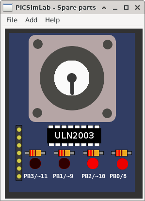
[Arduino_Uno/atmega328p/stepper_onerevolution] Stepper Motor Control - one revolutionThis program drives a unipolar or bipolar stepper motor. The motor is attached to digital pins 8 - 11 of the Arduino. The motor should revolve one revolution in one direction, then one revolution in the other direction. Created 11 Mar. 2007 Modified 30 Nov. 2009 by Tom Igoestepper_oneRevolution.ino | |
 |
Download (pzw)
View Online |
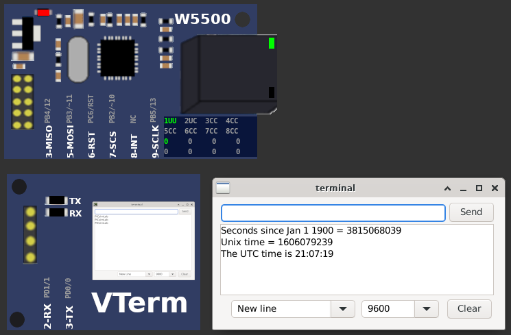
[Arduino_Uno/atmega328p/udpntpclient] library Ethernet example: UdpNtpClientUdp NTP Client Get the time from a Network Time Protocol (NTP) time server Demonstrates use of UDP sendPacket and ReceivePacket For more on NTP time servers and the messages needed to communicate with them, see http://en.wikipedia.org/wiki/Network_Time_Protocol created 4 Sep 2010 by Michael Margolis modified 9 Apr 2012 by Tom Igoe modified 02 Sept 2015 by Arturo Guadalupi This code is in the public domain.UdpNtpClient.ino | |
 |
Download (pzw) |
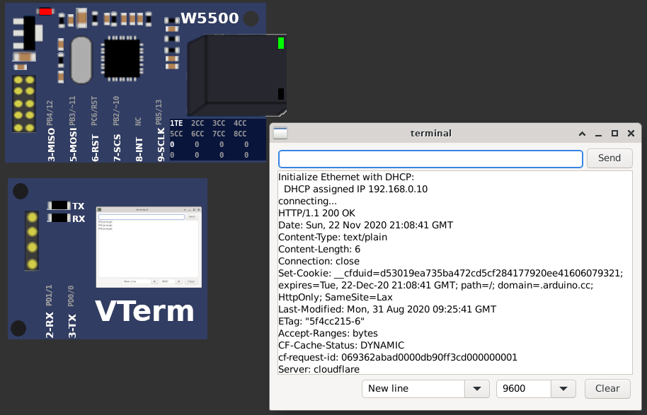
[Arduino_Uno/atmega328p/webclientrepeating] library Ethernet example: WebClientRepeatingRepeating Web client This sketch connects to a a web server and makes a request using a Wiznet Ethernet shield. You can use the Arduino Ethernet shield, or the Adafruit Ethernet shield, either one will work, as long as it's got a Wiznet Ethernet module on board. This example uses DNS, by assigning the Ethernet client with a MAC address, IP address, and DNS address. Circuit: * Ethernet shield attached to pins 10, 11, 12, 13 created 19 Apr 2012 by Tom Igoe modified 21 Jan 2014 by Federico Vanzati http://www.arduino.cc/en/Tutorial/WebClientRepeating This code is in the public domain.WebClientRepeating.ino | |
 |
Download (pzw) |
[Arduino_Uno/atmega328p/webserver] library Ethernet example: WebServerWeb Server A simple web server that shows the value of the analog input pins. using an Arduino Wiznet Ethernet shield. Circuit: * Ethernet shield attached to pins 10, 11, 12, 13 * Analog inputs attached to pins A0 through A5 (optional) created 18 Dec 2009 by David A. Mellis modified 9 Apr 2012 by Tom Igoe modified 02 Sept 2015 by Arturo Guadalupi Open a browser on address http://127.0.0.1:2080 WebServer.ino | |
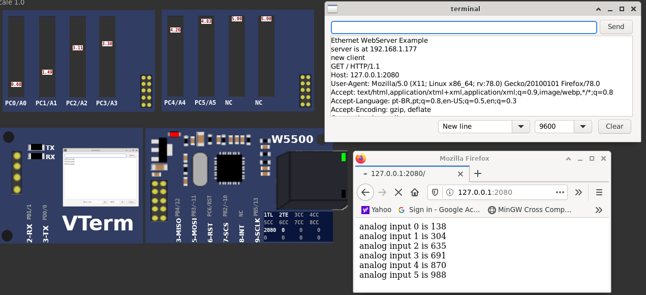 |
Download (pzw) |
[Blue_Pill/stm32f103c8t6/Bmp180_Rust] BMP180 - Bare-metal Rust Development with PICSimLabOriginal Link: https://github.com/Doulos/Embedded-Rust-with-PicSimLabSource code | |
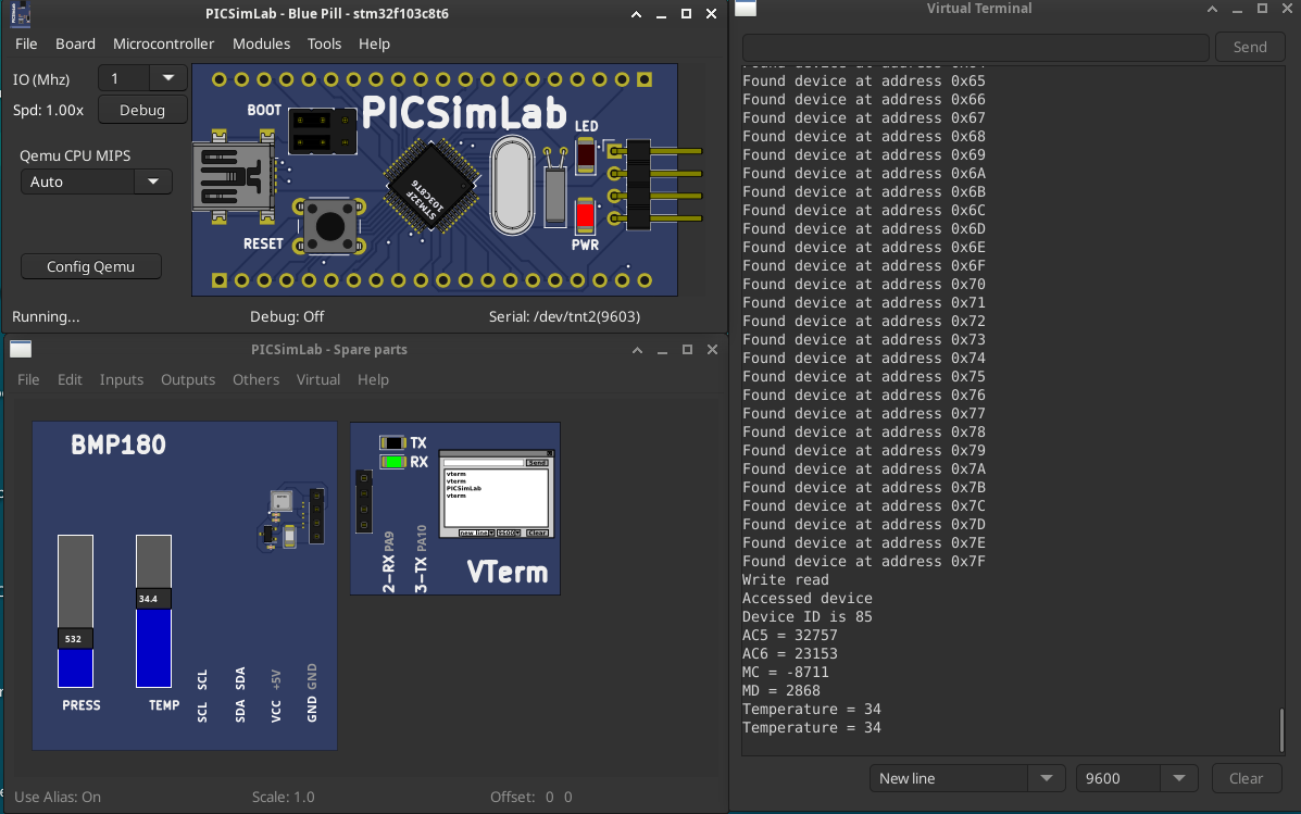 |
Download (pzw) |
[Blue_Pill/stm32f103c8t6/DS1621] DS1621 I2CSimple arduino reader for the DS1621 I2C temperature sensorSource code | |
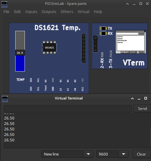 |
Download (pzw) |
[Breadboard/PIC16F777/test_b0]Simple example for testing board features.1- Ask to turn on all dip switches; 2- Tests LCD display; 3- Tests 7-segment displays; 4- Test the red LEDs connected to the PORTB and PORTD; 5- Tests push buttons; 6- Test the serial port transmitting; 7- Test the serial port receiving; 8- Tests AD converters connected to potentiometers; 9- Test Relays 10- Tests temperature measurement; 11- Turn on the Heater; 12- Turn on the fan and measure the speed. 13- Tests the matrix keyboard 14- Tests internal eepromMPLABX test_b0 project | |
 |
Download (pzw)
View Online |
[Breadboard/PIC16F877A/test_b0]Simple example for testing board features.1- Ask to turn on all dip switches; 2- Tests LCD display; 3- Tests 7-segment displays; 4- Test the red LEDs connected to the PORTB and PORTD; 5- Tests push buttons; 6- Test the serial port transmitting; 7- Test the serial port receiving; 8- Tests AD converters connected to potentiometers; 9- Test Relays 10- Tests temperature measurement; 11- Turn on the Heater; 12- Turn on the fan and measure the speed. 13- Tests the matrix keyboard 14- Tests internal eepromMPLABX test_b0 project | |
 |
Download (pzw)
View Online |
[Breadboard/PIC18F452/test_b0]Simple example for testing board features.1- Ask to turn on all dip switches; 2- Tests LCD display; 3- Tests 7-segment displays; 4- Test the red LEDs connected to the PORTB and PORTD; 5- Tests push buttons; 6- Test the serial port transmitting; 7- Test the serial port receiving; 8- Tests AD converters connected to potentiometers; 9- Test Relays 10- Tests temperature measurement; 11- Turn on the Heater; 12- Turn on the fan and measure the speed. 13- Tests the matrix keyboard 14- Tests internal eepromMPLABX test_b0 project | |
 |
Download (pzw)
View Online |
[Breadboard/PIC18F4550/test_b0]Simple example for testing board features.1- Ask to turn on all dip switches; 2- Tests LCD display; 3- Tests 7-segment displays; 4- Test the red LEDs connected to the PORTB and PORTD; 5- Tests push buttons; 6- Test the serial port transmitting; 7- Test the serial port receiving; 8- Tests AD converters connected to potentiometers; 9- Test Relays 10- Tests temperature measurement; 11- Turn on the Heater; 12- Turn on the fan and measure the speed. 13- Tests the matrix keyboard 14- Tests internal eepromMPLABX test_b0 project | |
 |
Download (pzw)
View Online |
[Breadboard/PIC18F4620/Aqua18F]Cooler controller for aquarium with meteorological measurement.The cooler output is turned on when the aquarium water temperature rises above 29C and off when it drops below 28.8C (hysteresis).MPLABX Aqua18F project | |
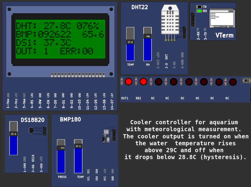 |
Download (pzw)
View Online |
[Breadboard/PIC18F4620/test_b0]Simple example for testing board features.1- Ask to turn on all dip switches; 2- Tests LCD display; 3- Tests 7-segment displays; 4- Test the red LEDs connected to the PORTB and PORTD; 5- Tests push buttons; 6- Test the serial port transmitting; 7- Test the serial port receiving; 8- Tests AD converters connected to potentiometers; 9- Test Relays 10- Tests temperature measurement; 11- Turn on the Heater; 12- Turn on the fan and measure the speed. 13- Tests the matrix keyboard 14- Tests internal eepromMPLABX test_b0 project | |
 |
Download (pzw)
View Online |
[ESP32_C3_DevKitC_02/ESP32-C3/ESP-NOW] Espressif ESP-NOW Example/* This example shows how to use ESPNOW. Prepare two device, one for sending ESPNOW data and another for receiving ESPNOW data. */ Build instructions and Source code | |
 |
Download (pzw) |
[ESP32_C3_DevKitC_02/ESP32-C3/idf_blink] Espressif ESP32-C3 Blink Example/* Blink Example This example code is in the Public Domain (or CC0 licensed, at your option.) Unless required by applicable law or agreed to in writing, this software is distributed on an "AS IS" BASIS, WITHOUT WARRANTIES OR CONDITIONS OF ANY KIND, either express or implied. */ Build instructions and Source code | |
 |
Download (pzw) |
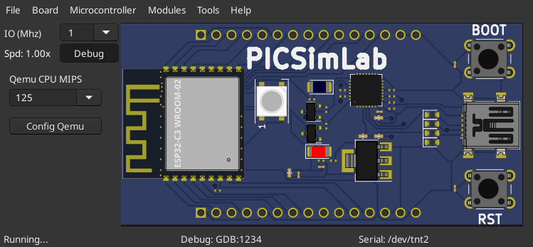
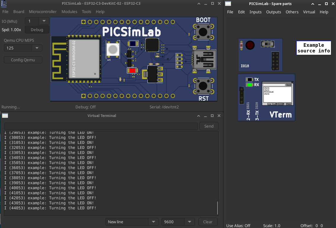
[ESP32_C3_DevKitC_02/ESP32-C3/SimpleWifiServer] WiFi Web Server LED BlinkA simple web server that lets you blink an LED via the web. This sketch will print the IP address of your WiFi Shield (once connected) to the Serial monitor. From there, you can open that address in a web browser to turn on and off the LED on pin 5. If the IP address of your shield is yourAddress: http://yourAddress/H turns the LED on http://yourAddress/L turns it off This example is written for a network using WPA encryption. For WEP or WPA, change the Wifi.begin() call accordingly. Circuit: * WiFi shield attached * LED attached to pin 5 created for arduino 25 Nov 2012 by Tom Igoe ported for sparkfun esp32 31.01.2017 by Jan Hendrik Berlin On PICSimLab qemu-esp32 simulator the Web server address is mapped in http://localhost:16555 Source code | |
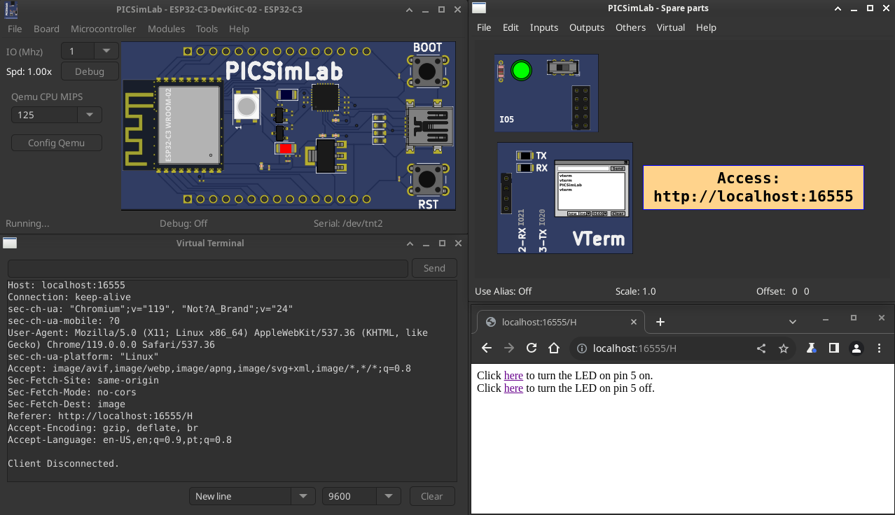 |
Download (pzw) |
[ESP32_DevKitC/ESP32/AdcMeasuring] ESP32 ADC with Arduino IDEMeasuring voltage example Source code | |
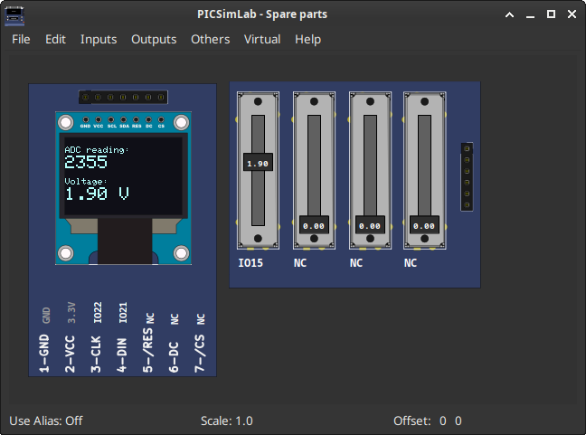 |
Download (pzw) |
[ESP32_DevKitC/ESP32/Bmp280Test] BMP280 Pressure sensorThis is a library for the BMP280 humidity, temperature & pressure sensor Designed specifically to work with the Adafruit BMP280 Breakout ----> http://www.adafruit.com/products/2651 These sensors use I2C or SPI to communicate, 2 or 4 pins are required to interface. Adafruit invests time and resources providing this open source code, please support Adafruit andopen-source hardware by purchasing products from Adafruit! Written by Limor Fried & Kevin Townsend for Adafruit Industries. BSD license, all text above must be included in any redistribution bmp280test.ino | |
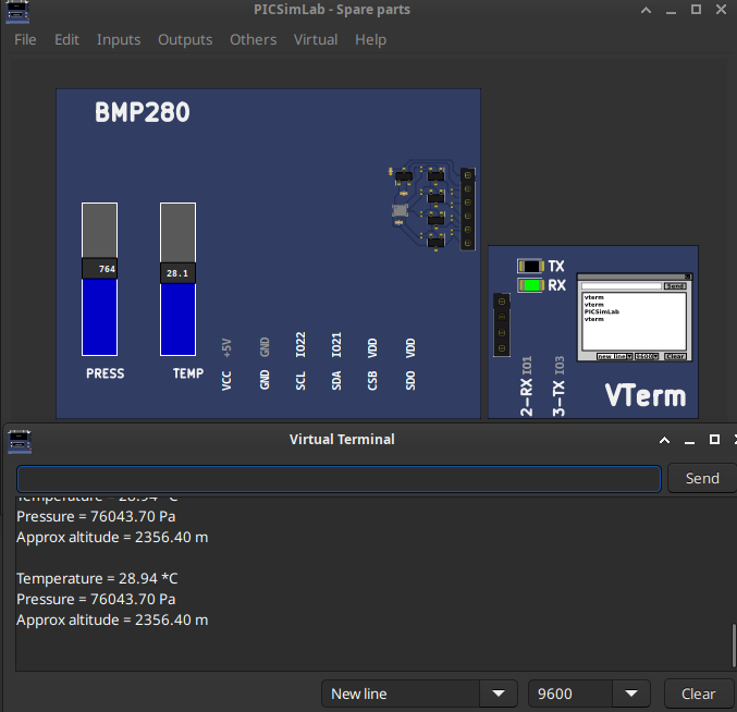 |
Download (pzw) |
[ESP32_DevKitC/ESP32/ESP-NOW] Espressif ESP-NOW Example/* This example shows how to use ESPNOW. Prepare two device, one for sending ESPNOW data and another for receiving ESPNOW data. */ Build instructions and Source code | |
 |
Download (pzw) |
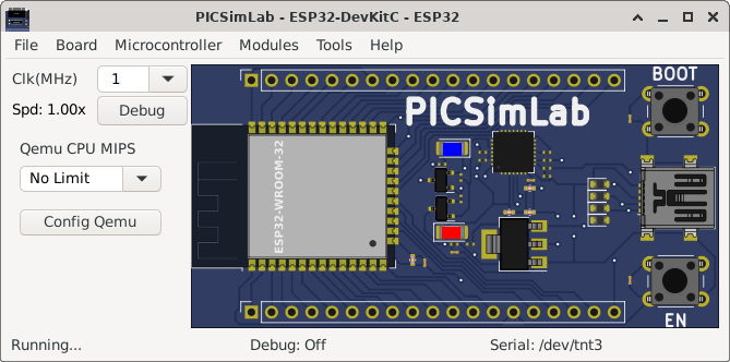
[ESP32_DevKitC/ESP32/idf_blink] Espressif ESP32 Blink Example/* Blink Example This example code is in the Public Domain (or CC0 licensed, at your option.) Unless required by applicable law or agreed to in writing, this software is distributed on an "AS IS" BASIS, WITHOUT WARRANTIES OR CONDITIONS OF ANY KIND, either express or implied. */ Build instructions and Source code | |
 |
Download (pzw) |
[ESP32_DevKitC/ESP32/micropython] ESP32 MicropythonOriginal Link: https://micropython.org/Before use this example it is necessary to configure a serial port emulator as described in the documentation. You can load the test code below using a serial terminal or an editor like Thonny or Mu. import machine import time led = machine.Pin(2, machine.Pin.OUT) while True: led.value(1) time.sleep(1) led.value(0) time.sleep(1) | |
 |
Download (pzw) |
[ESP32_DevKitC/ESP32/NuttX_led] Blink LED no ESP32 com o RTOS NuttXExemplo simples de como piscar um LED utilizando o RTOS Nuttx no ESP32 escrito por Sara Monteiro. | |
 |
Download (pzw) |
[ESP32_DevKitC/ESP32/SimpleWifiServer] WiFi Web Server LED BlinkA simple web server that lets you blink an LED via the web. This sketch will print the IP address of your WiFi Shield (once connected) to the Serial monitor. From there, you can open that address in a web browser to turn on and off the LED on pin 5. If the IP address of your shield is yourAddress: http://yourAddress/H turns the LED on http://yourAddress/L turns it off This example is written for a network using WPA encryption. For WEP or WPA, change the Wifi.begin() call accordingly. Circuit: * WiFi shield attached * LED attached to pin 5 created for arduino 25 Nov 2012 by Tom Igoe ported for sparkfun esp32 31.01.2017 by Jan Hendrik Berlin On PICSimLab qemu-esp32 simulator the Web server address is mapped in http://localhost:16555 Source code | |
 |
Download (pzw) |
[ESP32_DevKitC/ESP32/zephyr_esp32_led] Blink LED no ESP32 e Zephyr RTOSExemplo simples de como piscar um LED utilizando o RTOS Zephyr no ESP32 escrito por Glauber Ferreira. | |
 |
Download (pzw) |
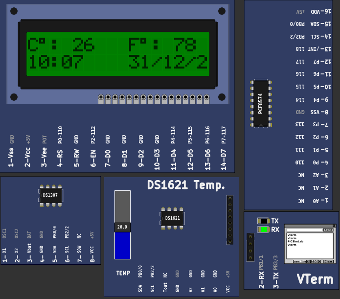
[Franzininho_DIY/attiny85/Tiny85_Temp_LCD_RTC] Example Tiny85 Temp LCD RTC of TinyWireM libraryATtiny85 as an I2C Master Ex3 BroHogan 1/22/11 I2C master reading DS1621 temperature sensor & DS1307 RTC. Display to I2C GPIO LED. SETUP: ATtiny Pin 1 = (RESET) N/U ATtiny Pin 2 = (D3) N/U ATtiny Pin 3 = (D4) to LED1 ATtiny Pin 4 = GND ATtiny Pin 5 = SDA on all devices ATtiny Pin 6 = (D1) to LED2 ATtiny Pin 7 = SCK on all devices ATtiny Pin 8 = VCC (2.7-5.5V) NOTE! - It's very important to use pullups on the SDA & SCL lines! DS1621 wired per data sheet. This ex assumes A0-A2 are set LOW for an addeess of 0x48 DS1307 wired per data sheet. This ex assumes A0-A2 are set LOW for an addeess of 0x68 PCA8574A GPIO was used wired per instructions in "info" folder in the LiquidCrystal_I2C lib. This ex assumes A0-A2 are set HIGH for an addeess of 0x3F LiquidCrystal_I2C lib was modified for ATtiny - on Playground with TinyWireM lib. TinyWireM USAGE & CREDITS: - see TinyWireM.h Link to source code: Tiny85_Temp_LCD_RTC.pde | |
 |
Download (pzw)
View Online |
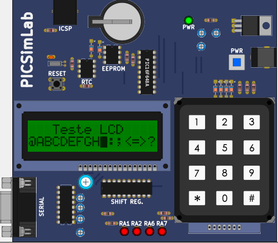
[K16F/PIC16F628A/test_b2]Simple example for testing board features.1- Tests LCD display; 2- Test the red LEDs connected to the PORTA. 3- Tests matrix keyboard 4- External eeprom test 24LC512 5- Test RTC PCF8563 6- Test serial port sending 7- Tests receiving serial port 8- Read keyboard and send through serial portMPLABX test_b2 project Others compilers test_b2 project | |
 |
Download (pzw)
View Online |
[K16F/PIC16F648A/test_b2]Simple example for testing board features.1- Tests LCD display; 2- Test the red LEDs connected to the PORTA. 3- Tests matrix keyboard 4- External eeprom test 24LC512 5- Test RTC PCF8563 6- Test serial port sending 7- Tests receiving serial port 8- Read keyboard and send through serial portMPLABX test_b2 project Others compilers test_b2 project | |
 |
Download (pzw)
View Online |
[McLab2/PIC16F777/test_b3]
Simple example for testing board features.1- Tests LCD display; 2- Tests 7-segment displays; 2- Test the red LEDs; 3- Tests push buttons; 4- Tests internal eeprom; 5- Tests external eeprom 24C04; 6- Test serial sending and receiving data; 7- Tests AD converter connected to the potentiometer; 8- Tests temperature measurement; 9- Turn on the Heater; 10- Turn on the fan and measure the speed.MPLABX test_b3 project Others compilers test_b3 project | |
 |
Download (pzw)
View Online |
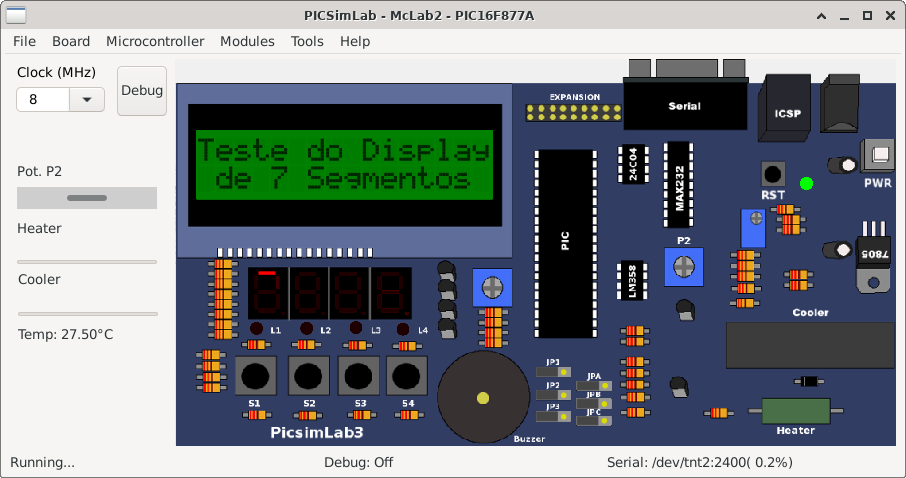
[McLab2/PIC16F877A/conectando_o_pic_09]
CONECTANDO O PIC - RECURSOS AVANÇADOS; ESTE EXEMPLO FOI ELABORADO PARA EXPLICAR O FUNCIONAMENTO DA USART DO PIC. ; O SOFTWARE CONVERTE O CANAL 1 DO CONVERSOR A/D (POTENCIÔMETRO P2) E MOSTRA ; NO DISPLAY O VALOR CONVERTIDO EM DECIMAL E HAXADECIMAL. ; ALÉM DE MOSTRAR O VALOR NO DISPLAY, O SOFTWARE TRANSMITE PELA USART O VALOR ; DA CONVERSÃO. OS VALORES RECEBIDOS PELA USART TAMBÉM SÃO MOSTRADOS NO LCD ; COMO CARACTERES ASCII.asm2-e09.asm | |
 |
Download (pzw)
View Online |
[McLab2/PIC16F877A/Demo_Mclab2]
Demo_Mclab2_16F877APrograma de teste da placa Mclab2 (somente arquivo binário .hex) 1- Testa display LCD; 2- Testa displays de 7 segmentos; 2- Testa os LEDs vermelhos; 3- Testa botões de pressão; 4- Testa eeprom interna; 5- Testa eeprom externa 24C04; 6- Testa porta serial envio; 7- Testa porta serial recebimento; 8- Testa conversor AD ligado ao potênciometro; 9- Testa medição de temperatura; 10- Liga Aquecedor; 11 -Liga ventilador e mede a velocidade. | |
 |
Download (pzw)
View Online |
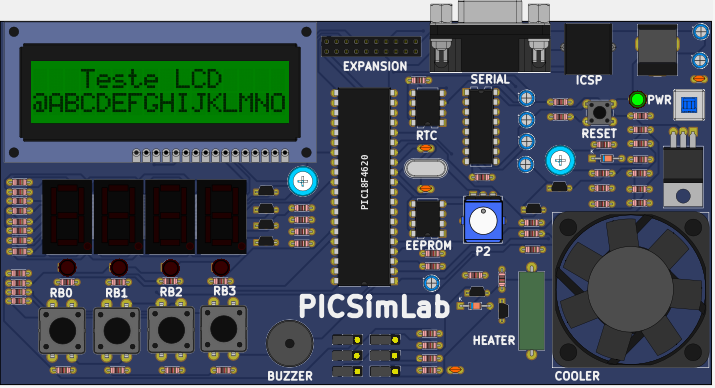
[McLab2/PIC16F877A/test_b3]
Simple example for testing board features.1- Tests LCD display; 2- Tests 7-segment displays; 2- Test the red LEDs; 3- Tests push buttons; 4- Tests internal eeprom; 5- Tests external eeprom 24C04; 6- Test serial sending and receiving data; 7- Tests AD converter connected to the potentiometer; 8- Tests temperature measurement; 9- Turn on the Heater; 10- Turn on the fan and measure the speed.MPLABX test_b3 project Others compilers test_b3 project | |
 |
Download (pzw)
View Online |
[McLab2/PIC18F4520/test_b3]
Simple example for testing board features.1- Tests LCD display; 2- Tests 7-segment displays; 2- Test the red LEDs; 3- Tests push buttons; 4- Tests internal eeprom; 5- Tests external eeprom 24C04; 6- Test serial sending and receiving data; 7- Tests AD converter connected to the potentiometer; 8- Tests temperature measurement; 9- Turn on the Heater; 10- Turn on the fan and measure the speed.MPLABX test_b3 project Others compilers test_b3 project | |
 |
Download (pzw)
View Online |
[McLab2/PIC18F452/test_b3]
Simple example for testing board features.1- Tests LCD display; 2- Tests 7-segment displays; 2- Test the red LEDs; 3- Tests push buttons; 4- Tests internal eeprom; 5- Tests external eeprom 24C04; 6- Test serial sending and receiving data; 7- Tests AD converter connected to the potentiometer; 8- Tests temperature measurement; 9- Turn on the Heater; 10- Turn on the fan and measure the speed.MPLABX test_b3 project Others compilers test_b3 project | |
 |
Download (pzw)
View Online |
[McLab2/PIC18F4550/test_b3]
Simple example for testing board features.1- Tests LCD display; 2- Tests 7-segment displays; 2- Test the red LEDs; 3- Tests push buttons; 4- Tests internal eeprom; 5- Tests external eeprom 24C04; 6- Test serial sending and receiving data; 7- Tests AD converter connected to the potentiometer; 8- Tests temperature measurement; 9- Turn on the Heater; 10- Turn on the fan and measure the speed.MPLABX test_b3 project Others compilers test_b3 project | |
 |
Download (pzw)
View Online |
[McLab2/PIC18F4620/test_b3]
Simple example for testing board features.1- Tests LCD display; 2- Tests 7-segment displays; 2- Test the red LEDs; 3- Tests push buttons; 4- Tests internal eeprom; 5- Tests external eeprom 24C04; 6- Test serial sending and receiving data; 7- Tests AD converter connected to the potentiometer; 8- Tests temperature measurement; 9- Turn on the Heater; 10- Turn on the fan and measure the speed.MPLABX test_b3 project Others compilers test_b3 project | |
 |
Download (pzw)
View Online |
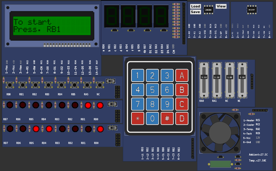
[PICGenios/PIC16F777/test_b4]Simple example for testing board features.1- Ask to turn on all dip switches; 2- Tests LCD display; 3- Tests 7-segment displays; 4- Test the red LEDs connected to the PORTB and PORTD; 5- Tests push buttons; 6- Test the serial port transmitting; 7- Test the serial port receiving; 8- Tests AD converters connected to potentiometers; 9- Test Relays 10- Tests temperature measurement; 11- Turn on the Heater; 12- Turn on the fan and measure the speed. 13- Tests the matrix keyboard 14- Tests internal eepromMPLABX test_b4 project Others compilers test_b4 project | |
 |
Download (pzw)
View Online |
[PICGenios/PIC16F877A/test_b4]Simple example for testing board features.1- Ask to turn on all dip switches; 2- Tests LCD display; 3- Tests 7-segment displays; 4- Test the red LEDs connected to the PORTB and PORTD; 5- Tests push buttons; 6- Test the serial port transmitting; 7- Test the serial port receiving; 8- Tests AD converters connected to potentiometers; 9- Test Relays 10- Tests temperature measurement; 11- Turn on the Heater; 12- Turn on the fan and measure the speed. 13- Tests the matrix keyboard 14- Tests internal eepromMPLABX test_b4 project Others compilers test_b4 project | |
 |
Download (pzw)
View Online |
[PICGenios/PIC18F4520/test_b4]Simple example for testing board features.1- Ask to turn on all dip switches; 2- Tests LCD display; 3- Tests 7-segment displays; 4- Test the red LEDs connected to the PORTB and PORTD; 5- Tests push buttons; 6- Test the serial port transmitting; 7- Test the serial port receiving; 8- Tests AD converters connected to potentiometers; 9- Test Relays 10- Tests temperature measurement; 11- Turn on the Heater; 12- Turn on the fan and measure the speed. 13- Tests the matrix keyboard 14- Tests internal eepromMPLABX test_b4 project Others compilers test_b4 project | |
 |
Download (pzw)
View Online |
[PICGenios/PIC18F452/test_b4]Simple example for testing board features.1- Ask to turn on all dip switches; 2- Tests LCD display; 3- Tests 7-segment displays; 4- Test the red LEDs connected to the PORTB and PORTD; 5- Tests push buttons; 6- Test the serial port transmitting; 7- Test the serial port receiving; 8- Tests AD converters connected to potentiometers; 9- Test Relays 10- Tests temperature measurement; 11- Turn on the Heater; 12- Turn on the fan and measure the speed. 13- Tests the matrix keyboard 14- Tests internal eepromMPLABX test_b4 project Others compilers test_b4 project | |
 |
Download (pzw)
View Online |
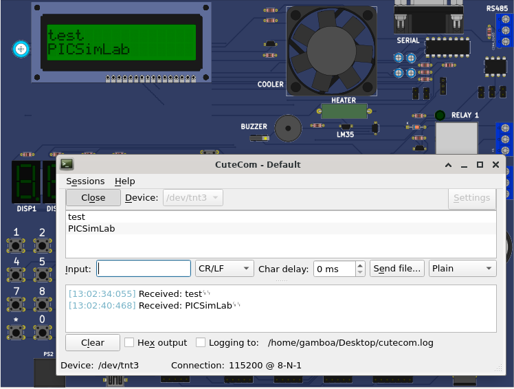
[PICGenios/PIC18F4550/Serial_lcd]Serial/LCD simple test.Open the serial term and type lines with LF terminator.MPLABX Serial_lcd project | |
 |
Download (pzw)
View Online |
[PICGenios/PIC18F4550/test_b4]Simple example for testing board features.1- Ask to turn on all dip switches; 2- Tests LCD display; 3- Tests 7-segment displays; 4- Test the red LEDs connected to the PORTB and PORTD; 5- Tests push buttons; 6- Test the serial port transmitting; 7- Test the serial port receiving; 8- Tests AD converters connected to potentiometers; 9- Test Relays 10- Tests temperature measurement; 11- Turn on the Heater; 12- Turn on the fan and measure the speed. 13- Tests the matrix keyboard 14- Tests internal eepromMPLABX test_b4 project Others compilers test_b4 project | |
 |
Download (pzw)
View Online |
[PICGenios/PIC18F45K50/test_b4]Simple example for testing board features.1- Ask to turn on all dip switches; 2- Tests LCD display; 3- Tests 7-segment displays; 4- Test the red LEDs connected to the PORTB and PORTD; 5- Tests push buttons; 6- Test the serial port transmitting; 7- Test the serial port receiving; 8- Tests AD converters connected to potentiometers; 9- Test Relays 10- Tests temperature measurement; 11- Turn on the Heater; 12- Turn on the fan and measure the speed. 13- Tests the matrix keyboard 14- Tests internal eepromMPLABX test_b4 project Others compilers test_b4 project | |
 |
Download (pzw)
View Online |
[PICGenios/PIC18F4620/test_b4]Simple example for testing board features.1- Ask to turn on all dip switches; 2- Tests LCD display; 3- Tests 7-segment displays; 4- Test the red LEDs connected to the PORTB and PORTD; 5- Tests push buttons; 6- Test the serial port transmitting; 7- Test the serial port receiving; 8- Tests AD converters connected to potentiometers; 9- Test Relays 10- Tests temperature measurement; 11- Turn on the Heater; 12- Turn on the fan and measure the speed. 13- Tests the matrix keyboard 14- Tests internal eepromMPLABX test_b4 project Others compilers test_b4 project | |
 |
Download (pzw)
View Online |
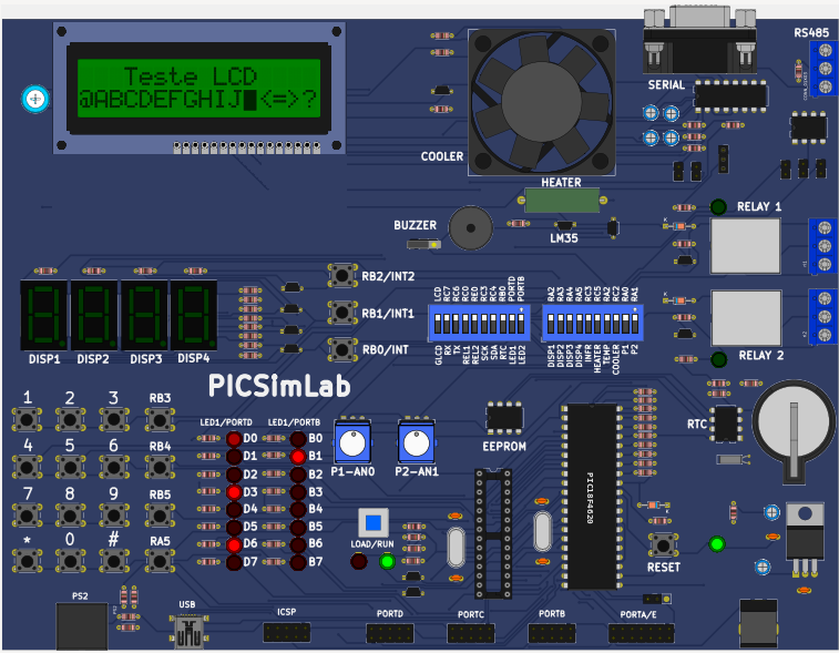
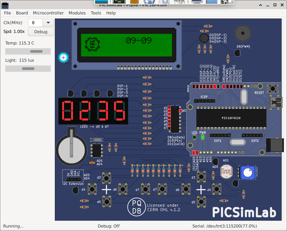
[PQDB/PIC18F4520/pqdb_full_demo]Example for testing all board features.1- Potentiometer value is shown in 7 segment display; 2- LCD prints seconds value from main code counter and the DS1307; 3- Swiches values are printed on LCD when Pressed; 4- Switch 'S' turn on buzzer via PWM; 6- RGB led is flashin (pins are multiplexed with other componentes); 7- Serial port in Ecco mode (send what ir receive);MPLABX full demo project | |
 |
Download (pzw)
View Online |
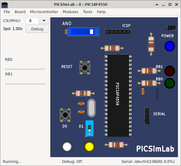
[X/PIC18F4550/Test_x]Simple board X exampleSimple example to use ADC ,switches and button inputs to control LEDs on outputs.Based on board of tutorial Creating New Boards. MPLABX board_x.X project | |
 |
Download (pzw)
View Online |